UART
UART(universal asynchronous receiver / transmitter)
Intro
UART stands for universal asynchronous receiver / transmitter and defines a protocol, or set of rules, for exchanging serial data between two devices.
- UART is very simple and only uses two wires between transmitter and receiver to transmit and receive in both directions.
- UART was one of the earliest serial protocols.
Advantage
A UART may be used when
- High speed is not required
- An inexpensive communication link between two devices is required
- UART communication is very cheap
- Single wire for each direction(and ground wire).
- Simple hardware.
Principle
In UART communication, two UARTs communicate directly with each other
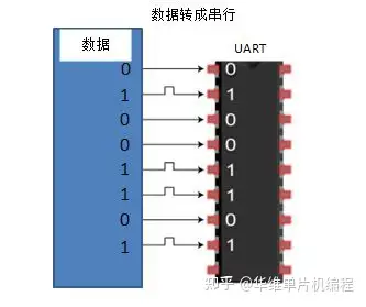
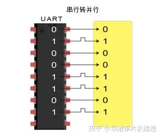
The transmitting UART converts parallel data from a controlling device like a CPU into serial form, transmits it in serial to the receiving UART, which then converts the serial data back into parallel data for the receiving device.
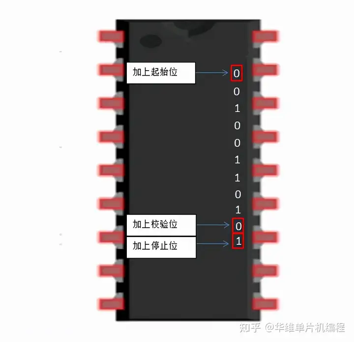
The UART that is going to transmit data receives the data from a data bus. The data bus is used to send data to the UART by another device like a CPU. Data is transferred from the data bus to the transmitting UART in parallel form. After the transmitting UART gets the parallel data from the data bus, it adds a start bit, a parity bit, and a stop bit, creating the data packet.
在 UART 通信中,两个 UART 直接相互通信。发送端将来自控制设备(如 CPU)的并行数据转换为串行形式,接着将其串行传输到接收端,然后接收端将串行数据转换回并行数据以供接收设备使用。
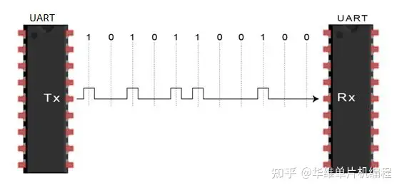
数据从一个UART的发送引脚(Tx) 流向另一个UART的接收(Rx) 引脚
Simplex(单工
Uni-directional flow of data
In only one direction
UART只用Tx或Rx其中一根线进行通讯,也就是只作接收或发送
Half duplex(半双工
Bi-directional flow of data (one direction at a time.)
In both direction, but only one TX and one RX at a time
UART在同一时间,只用作发送或接收
Full duplex(全双工
Bi-directional flow of data in both directions at the same time (simultaneous flow).
Both sides can transmit and receive in the same time
UART在发送的同时,也可以接收
Protocol
Each character is sent as
- a logic low start bit
- a configurable number of data bits (usually 7 or 8, sometimes 5)
- an optional parity bit
- one or more logic high stop bits
- with a particular bit timing (“baud”)
When the receiving UART detects a start bit, it starts to read the incoming bits at a specific frequency known as the baud rate. Baud rate is a measure of the speed of data transfer, expressed in bits per second (bps).
Both UARTs must operate at about the same baud rate. The baud rate between the transmitting and receiving UARTs can only differ by about 10% before the timing of bits gets too far off.
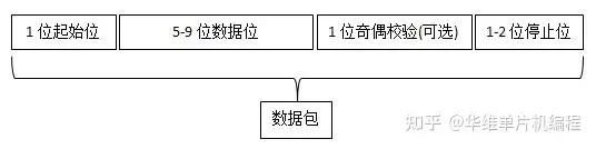
UART transmitted data is organized into packets. Each packet contains 1 start bit, 5 to 9 data bits (depending on the UART), an optional parity bit, and 1 or 2 stop bits:
Data Frame
The data frame contains the actual data being transferred. It can be 5 bits up to 8 bits long fi a parity bit is used.
if no parity bit is used, the data frame can be 9 bits long. In most cases, the data is sent with the least significant bit first.
UART属于异步传输数据,这意味着没有时钟信号将发送的位输出与接收的位采样同步,也就是发送与接收使用各自的时钟。发送端将开始和停止位添加到传输的数据帧中,通过数据帧中定义的开始位和结束位,接收端知道何时开始读取这些位。
每个数据帧包含 1 个起始位、5 到 9 个数据位(取决于 UART的设置,如果有奇偶校验位是5到8,没有则是5到9)、一个可选的奇偶校验位和 1 个或 2 个停止位:
Start bit
The UART data transmission line is normally held at a high voltage level when it’s not transmitting data.
To start the transfer of data, the transmitting UART pulls the transmission line from high to low for one clock cycle.
When the receiving UART detects the high to low voltage transition, it begins reading the bits in the data frame at the frequency of the baud rate.
UART 数据传输线在不传输数据时通常保持在高电平。要开始发送数据时,发送端UART先在一个时钟周期内将传输线从高电平拉到低电平。当接收端UART 检测到从高到低的电压转换时,它开始以设置好的波特率的频率读取数据帧中的位。
数据帧
数据帧包含正在传输的实际数据。如果使用奇偶校验位,它可以是 5 位到 8 位。如果不使用奇偶校验位,则数据帧可以是 9 位。在大多数情况下,首先发送的数据是最低有效位。
Parity
Parity describes the evenness or oddness of a number.
The parity bit is a way for the receiving UART to tell if any data has changed during transmission(Bits can be changed by electromagnetic radiation, mismatched baud rates, or long distance data transfers).
After the receiving UART reads the data frame, it counts the number of bits with a value of 1and checks if the total is an even or odd number.
If the parity bit is a 0 (even parity), the 1 bits in the data frame should total to an even number. If the parity bit is a 1 (odd parity), the 1 bits in the data frame should total to an odd number.
When the parity bit matches the data, the UART knows that the transmission was free of errors. But if the parity bit is a 0, and the total is odd; or the parity bit is a 1, and the total is even, the UART knows that bits in the data frame have changed.
奇偶校验位是接收端UART 判断数据在传输过程中是否发生变化的一种方式。位会因电磁辐射、不匹配的波特率或长距离数据传输而发生改变。接收端 UART 读取数据帧后,检查数据部分值为1的个数是奇数还是偶数。当奇偶校验位与数据匹配时,UART 知道传输没有错误。
Stop bits
To signal the end of the data packet, the sending UART drives the data transmission line from a low voltage to a high voltage for at least two bit durations.
发送端UART 将数据传输线从低电平拉到高电平持续至少两个位的时间来表示整个数据包的传输已经结束。
Receiver
All operations of the UART hardware are controlled by a clock signal which runs at a multiple of the data rate, typically 8 times the bit rate.
The receiver tests the state of the incoming signal on each clock pulse, looking for the beginning of the start bit.
Steps
The transmitting UART receives data in parallel from the data bus(UART 从数据总线并行接收数据
The transmitting UART adds the start bit, parity bit, and the stop bit(s) to the data frame(发送 UART 将起始位、奇偶校验位和停止位添加到数据帧
- The entire packet is sent serially from the transmitting UART to the receiving UART. The receiving UART samples the data line at the pre-configured baud rate(整个数据包从发送 UART 串行发送到接收 UART。接收 UART 以预配置的波特率对数据线进行采样:
- The receiving UART discards the start bit, parity bit, and stop bit from the data frame(接收 UART 丢弃数据帧中的起始位、奇偶校验位和停止位
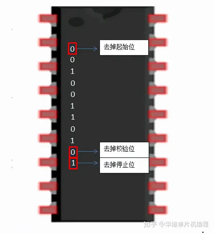
- The receiving UART converts the serial data back into parallel and transfers it to the data bus on the receiving end接收端 UART 将串行数据转换回并行,并将其传输到接收端的数据总线:
Error
Framing error
A “framing error” occurs when the designated “start” and “stop” bits are not found.
As the start” bit is used to identify the beginning of an incoming character, it acts as a reference for the remaining bits.
If the data line is not in the expected state (hi/lo) when the “stop” bit is expected, a Framing Error will occur.
Parity error
A Parity Error occurs when the parity of the number of 1 bits disagrees with that specified by the parity bit.
Use of a parity bit is optional, so this error will only occur if parity-checking has been enabled.
PHYSICAL LAYER STANDARDS
There are actually quite a number of different standards that utilizes similar protocol. For instances, TL level UART, RS-232, RS-422, RS-485 and etc. We will only discuss about TL level UART and RS-232 here.
TTL level uart
Most microcontrollers with UART Uses TTL (Transistor-transistor Logic) level UART. It is the simplest form of UART. Both logic 1and 0 are represented by 5V and OV respectively.
The TTL level UART is commonly used in the communications between microcontrollers and ICs. Only 2 wires are required for the full duplex communications as illustrated in the picture below
RS-232
RS-232 (Recommended Standard 232) is a standard for serial binary data signals connecting between a Data Terminal Equipment (DTE) and a Data Communication Equipment (DCE). It is commonly used in computer serial ports. One of the significant differences between TTL level UART and RS-232 is the voltage level. Valid signals in RS-232 are #3 to - #15V, and signals near OV is not a valid RS-232 level.
Besides voltage level, the RS-232 also has a few extra pins specifically designed for the communication between PC and modem. The pinouts of the DB-9 and their functions are shown below.
INTERFACING BETWEEN TTML LEVEL UART AND R$-232
From previous discussions, we know that microcontrollers make use of TTL level UART while the PC serial port uses RS-232. Since both standards uses similar software protocol, both of them are able to communicate via UART. However, because of the differences in voltage level and polarity, w e will need a level shifter to interface the TL level UART with the RS-232. Nowadays, this can be easily done with the commonly available IC such as the MAX232 from Maxim
Advantage & Disadvantage
Adv
Only uses two wires
No clock signal is necessary
Has a parity bit to allow for error checking
- The structure of the data packet can be changed as long as both sides are set up for it
- Well documented and widely used method
Disadv
The size of the data frame is limited to a maximum of 9 bits
Doesn’t support multiple slave or multiple master systems
The baud rates of each UART must be within 10% of each other
Conclusion
USART stands for Universal Synchronous Asynchronous Receiver Transmitter, it converts parallel data into serial data like UART.
UART peripheral supports only asynchronous mode, whereas USART supports both synchronous and asynchronous modes.
All modern microcontrollers come with a USART module instead of just a UART module.
You can use the USART module both in the synchronous mode as well as asynchronous mode.
In synchronous transmission, the clock is sent separately from the data stream, and no start/stop bits are used. This improves data transmission efficiency by avoiding the extra bits like start/stop, which are not useful data.